

Custom AC EMI Filters: Tailoring Electromagnetic Interference Solutions for Your Power System
2026-10-22
Power systems rarely hum in silence for long. As switching frequencies climb and layouts tighten, electromagnetic interference creeps into the most carefully designed equipment. Off-the-shelf EMI filters often force compromises—oversized footprints, mismatched attenuation curves, or connectors that never quite align. That’s where custom AC EMI filters change the equation. At DOREXS, we’ve seen how a tailored filter can turn a noisy prototype into a compliance-ready product without redesigning the entire power stage. This post walks through what makes custom AC EMI filtering different, when to choose it over standard parts, and how to specify the right characteristics for your system.
Reading the Noise Fingerprint of Your AC Power Rails
Every supply rail carries a signature shaped by its converters, board parasitics, and dynamic loads. Rather than chasing a single numeric ripple spec, you can treat the rail as a living signal and read its noise fingerprint. That fingerprint often reveals more about system health than a simple RMS or peak-to-peak measurement ever could.
Start by capturing the rail voltage with a high-bandwidth differential probe or a well-grounded passive probe, keeping the loop area tiny. Look beyond the switching frequency. You'll see ringing from hot-loop inductance, repetitive spikes from gate drive edges, and low-frequency wander driven by load transients. A spectrum view turns these into distinct lines and humps, each tied to a physical mechanism. Once you map those features, you have a baseline.
Comparing fingerprints before and after a board change, firmware tweak, or thermal cycle can expose marginal decoupling, aging capacitors, or layout issues that simulators miss. The noise may shift in frequency, amplitude, or harmonic pattern. Reading those shifts is closer to interpreting a diagnostic chart than just measuring ripple.
Custom Filter Topologies That Ditch the One-Size-Fits-All Mold
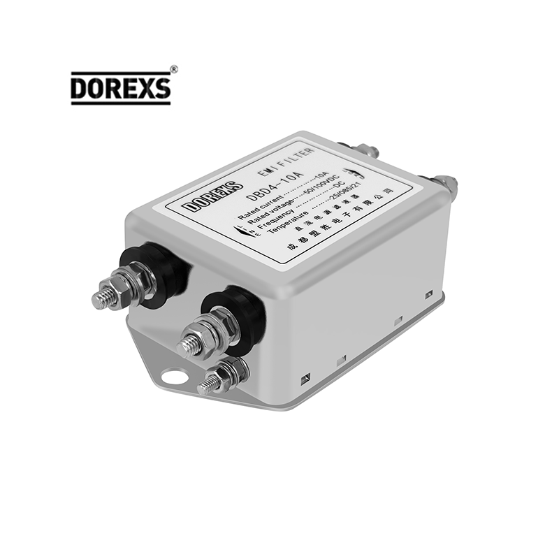
Most off-the-shelf filter designs assume a narrow set of operating conditions: a specific center frequency, a predictable bandwidth, and a substrate with convenient dielectric properties. The moment you move outside that comfort zone—odd fractional bandwidths, aggressive size limits, or a substrate stackup that was never meant for RF—the standard Chebyshev or Butterworth ladder starts fighting you. Custom topologies flip the script by letting the geometry follow the problem. Instead of forcing a known schematic into a board, you might start with a resonator shape that fits the available space and then tune coupling paths one by one until the insertion-loss ripple and return-loss nulls land where they should.
That kind of bespoke approach leans heavily on electromagnetic simulation and a fair bit of parameter sweeping. You often end up with structures that don't have clean textbook names: folded half-wave lines with asymmetric taps, dual-mode patches with notched corners, or grounded coplanar elements that borrow loading tricks from distributed amplifiers. The payoff is a filter that performs better in a specific design than any simplified cookbook topology could. It also means the result is less portable—small changes in board material or copper thickness can shift the response enough to warrant re-tuning. But for products that need to fit an unusual footprint or hit a demanding rejection mask, that trade-off usually beats wrestling with a generic prototype that never quite fits.
Selecting Core Materials for Attenuation That Survives Real Loads
Picking a core material that holds up under actual mechanical stress means looking past datasheet attenuation curves. The numbers you see for loss per meter assume a clean, unloaded sample sitting in a test fixture. Once the cable gets pulled around a corner, stepped on, or clamped into a harness, the effective permittivity and magnetic loss shift. Ferrite-loaded polymers, for example, can micro-crack when flexed repeatedly, creating small air gaps that quietly reduce attenuation at higher frequencies. You need a material that keeps its distributed losses even when the geometry is strained.
One practical approach is to test candidate cores inside a representative assembly, not as bare toroids or beads. Wrap the cable, add the connectors, apply the expected bend radius, and then measure insertion loss. Some nickel-zinc ferrites perform well on paper but lose more than 3 dB of suppression after a few hundred flex cycles because their brittle structure degrades. By contrast, certain carbonyl iron powders blended into a flexible elastomer maintain consistency because the particles can shift slightly without breaking the magnetic path. The trade-off is usually a lower initial permeability, which means thicker sections or shorter lengths for the same attenuation target.
Load survival also depends on how the core is mounted. A hard ferrite sleeve that is glued rigidly to a PCB can transmit vibration straight into the brittle material, leading to hairline fractures. A better detail is to leave a small compliant layer between the core and any hard point, or use a material that is inherently ductile while still providing common-mode impedance. After selecting a shortlist, run a quick thermal cycle plus vibration test on a real cable bundle; you will often see one material stand out not because of its spec sheet, but because it does not degrade after 500 cycles. That is the one to take forward.
Mechanical Integration Without Reworking Your Chassis
Most aftermarket upgrades demand cutting, drilling, or welding—work that permanently alters the chassis and often voids warranties. This system takes a different path. Every bracket, mount, and reinforcement is designed to align with existing factory holes and load paths. You don't need a torch, a plasma cutter, or a stack of shims. The parts slide into place using the same bolt locations the OEM engineers already validated.
The key is in the tolerance stack. Rather than forcing you to "make it fit," each component is machined to match the actual production variations of common chassis platforms. This means the transfer case, suspension links, or steering rack bolt up without binding, even on vehicles with years of road grime and minor misalignment. No slotting, no reaming, no stress risers introduced into the frame rails.
Because the chassis remains untouched, the original crumple zones and fatigue life stay intact. You also cut install time dramatically—most users finish the mechanical swap in a single afternoon with basic hand tools. If the vehicle ever needs to return to stock, the original hardware goes right back into the same untouched holes.
Bench Testing Beyond the Datasheet for Inrush and Transients
Datasheet specs for inrush current and transient response are typically captured under tightly controlled lab conditions—fixed input voltage, resistive load, room temperature, and a clean PCB layout. Real circuits rarely behave that politely. Stray inductance in cabling, bulk capacitance on the load side, and even the ESR of input capacitors can push actual inrush peaks well past the published maximum. That's why a bench test with a current probe and a fast oscilloscope is non-negotiable before committing a power stage to production.
Set up a hot-swap or load-step test that mimics the worst-case turn-on sequence. Use a low-inductance shunt or a Hall-effect current probe with at least 20 MHz bandwidth, and trigger the scope on the rising edge of the input voltage or the enable signal. Capture the current waveform for the first 50 to 200 microseconds—look for overshoot beyond the datasheet's inrush limit, ringing that suggests marginal phase margin, or a second current spike when downstream converters start up. For transient response, apply a fast load step (10% to 90% in under 1 microsecond) and watch both output voltage deviation and recovery time. Compare those numbers against the datasheet's load transient plots; if you're off by more than 20%, your layout or input filtering is probably to blame.
Don't trust a single capture—vary the input voltage from the minimum to maximum operating range and sweep the ambient temperature if possible. Some converters behave fine at room temp but fold back or oscillate at cold start. Also probe the input supply rail during the inrush event: a sag of more than a few hundred millivolts can trip undervoltage lockout or cause a brownout reset. The goal isn't to prove the datasheet wrong, but to map the real operating envelope so your protection circuitry (fuses, MOSFET SOA, eFuse timers) gets sized for the transient you'll actually see, not the one the marketing team printed.
Balancing Compliance and Efficiency Without Over-Filtering
Compliance often gets painted as a rigid checklist, but in practice, the smartest teams treat it as a living framework. The goal is not to block every questionable item at the gate—it's to catch genuine risks early while letting legitimate work move at full speed. When filters are tuned too aggressively, false positives pile up, employees find workarounds, and the whole system loses credibility. A better approach starts with mapping each rule to its real-world impact: is this requirement about preventing fraud, protecting privacy, or simply following an internal convention? Once you know the “why,” you can set thresholds that reflect actual tolerance for error.
Efficiency doesn’t mean bypassing checks; it means designing them to be almost invisible. Think of a well-run airport security line: most people walk through without a pat-down because the baseline screening is quick and predictable. Only when something triggers a specific, well-understood alert does a human step in. Translate that to your workflow—automated validation for the obvious cases, human review only for edge conditions. For example, if a document needs three approvals, make sure the first two are straightforward and instant, and reserve the third for a focused look at unusual patterns. That way, you’re not filtering out creativity or speed; you’re filtering out genuine mistakes.
The trap of over-filtering often comes from fear: someone once got burned, so now every request gets the same heavy scrutiny. But blanket strictness is a blunt tool that slows everyone down without meaningfully reducing risk. Instead, use sampling and feedback loops—review a small percentage of low-risk items after the fact, and if error rates stay low, loosen the pre-approval steps. This builds trust over time and lets compliance act like a safety net rather than a brick wall. When efficiency and compliance pull in the same direction, the organization can move fast without tripping over its own rules.
FAQ
A custom filter matches the exact impedance, current rating, and frequency range of your equipment, so it suppresses noise precisely where your system generates or receives it. Off-the-shelf filters often force compromises in attenuation, size, or connection style.
Look for signs like repeated compliance failures, unusual voltage or current waveforms, tight space constraints, or non-standard connector requirements. If your power system operates outside typical industrial frequency bands or has high dv/dt transients, a custom design usually becomes necessary.
You need the nominal voltage, full-load current, operating frequency, required insertion loss across the conducted emissions range, ambient temperature, mounting orientation, and the exact standards you must meet. Clear mechanical drawings and photos of the surrounding enclosure also help.
Yes, but mainly conducted emissions on the AC mains side. However, a well-integrated custom filter with shielded housing and proper feedthrough capacitors can also reduce near-field coupling that contributes to radiated interference in the lower frequency spectrum.
Motor drives with long cable runs, medical imaging equipment with sensitive detectors, renewable energy inverters switching at high frequencies, and avionics test benches often need custom filters because their noise signatures and physical layouts are far from generic.
The inductor cores can be selected with lower permeability or an air gap, and the winding geometry can be adjusted to avoid saturation during brief current spikes. This keeps the filter effective while allowing large capacitors to charge safely.
Not necessarily. A custom filter can be built exactly to the required attenuation and enclosure footprint, which sometimes reduces size and cost by eliminating unnecessary stages or expensive components that a generic filter would include for broader coverage.
Check their ability to provide measured insertion loss curves under your actual load conditions, their experience with your specific safety standards, their prototyping turnaround time, and whether they offer thermal testing or pre-compliance support before finalizing the design.
Conclusion
A practical custom AC EMI filter begins with a close look at the actual noise present on your power rails. Instead of assuming a standard interference profile, engineers measure conducted emissions across line, neutral, and ground under real operating conditions. That measured noise fingerprint then drives the choice of filter topology. A single-stage LC network might handle a narrowband spike, while a multi-stage design with feedthrough capacitors or common-mode chokes becomes necessary when both differential and common-mode noise appear across a wide frequency range. The core materials matter just as much. Ferrite or nanocrystalline cores are selected not only for their permeability curves but for how they behave when the load draws significant current, since saturation or thermal drift can quickly erase the attenuation you measured on a lightly loaded bench.
Mechanical fit is another part of the custom approach. A filter can be built to match existing chassis cutouts, terminal blocks, and mounting points, so you avoid redesigning the enclosure or adding adapter plates. Bench testing then goes beyond what a typical datasheet covers: inrush current, repetitive transients, and line disturbances are applied to verify that the filter does not ring, overheat, or let spikes through during startup or load steps. Finally, the filter is tuned to pass the required conducted emissions limits without over-filtering. Too much capacitance can raise leakage current and reduce efficiency, while excessive inductance can cause voltage drop or resonance. The goal is a balanced design that meets compliance targets and keeps the power system stable under the loads you actually run.
Contact Us
Contact Person: Eric
Email: [email protected]
Tel/WhatsApp: 8618117837140
Website: https://www.emcdorexs.com