

High Precision Shunt Resistor Manufacturer Reveals Critical Design Considerations for Accurate Current Sensing
2026-07-06
Current sensing accuracy begins with one often-overlooked component: the shunt resistor. As applications demand tighter tolerances and higher reliability, the design choices behind these passive devices can make or break your measurements. In this article, Milliohm, a high-precision shunt resistor manufacturer, pulls back the curtain on the critical factors that engineers must weigh—from material selection to thermal management—to achieve precise, drift-free current monitoring.
Material Purity’s Overlooked Impact on Measurement Stability
Trace contaminants in materials are rarely front of mind when troubleshooting erratic readings, yet they often lie at the root of unexplained drift. A reagent labeled 99.9% pure may still contain ppm-level impurities that form micro-reaction zones, subtly altering conductivity or optical behavior over time. These effects accumulate gradually, mimicking sensor degradation or environmental fluctuations, and slip past routine calibrations.
The interplay between impurities and stability isn’t linear. Certain contaminants act catalytically, accelerating phase separation or interfacial reactions that suddenly shift baselines after days of apparent steadiness. For example, metallic residues in glass substrates have been shown to promote surface charging under varying humidity, turning a typically robust measurement setup into a moving target. Because the source material passes standard assays, these latent triggers remain invisible until long-term reliability tests expose them.
Addressing this blind spot demands a shift in how purity is perceived: not just a certificate number, but a dynamic contributor to the measurement’s temporal fingerprint. Pre-conditioning materials under operational conditions or mapping impurity distributions before integration can reveal subtle risks that batch-level specs miss. Ignoring these factors means accepting that every readout carries an unknown expiration date, quietly set by the very makeup of the matter under study.
When Milliohms Matter: Navigating Resistance Value Trade-offs
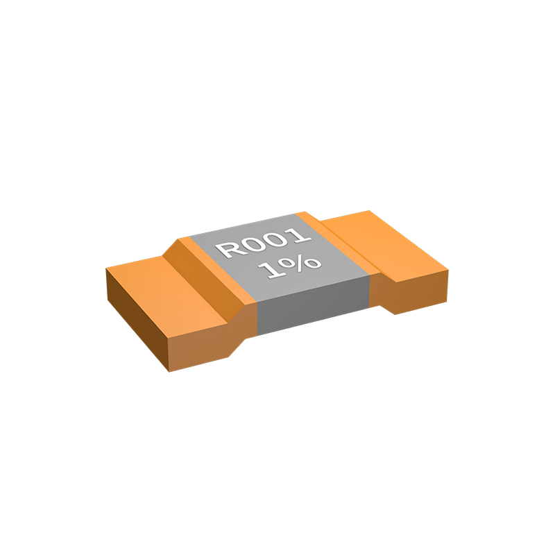
Resistance values are often treated as an afterthought in circuit design—until a few extra milliohms derail a precision measurement or cause thermal runaway in a power stage. When current levels creep into the tens of amps, what looks like a negligible trace resistance suddenly becomes a silent source of voltage sag, skewing analog readings and heating connectors beyond spec. It’s not just about picking a thick wire; the interplay between copper weight, via stitching, and even solder joint quality can swallow your voltage budget before the current even reaches the load.
But chasing zero ohms everywhere gets expensive fast. Wider pours eat board real estate, thicker copper adds material cost, and oversized connectors waste space. The trick is knowing where milliohms truly bite—like the sense lines of a Kelvin-connected current shunt, or the path between a battery and its protection IC. Trading a few milliohms in bulk power rails might be painless with adequate regulation, but in a feedback divider, a single miliohm drift in a via can shift a supply voltage out of tolerance over temperature. Designers who map out the actual current loops and run worst-case IR drop simulations early can spot these hotspots and allocate their “resistance budget” with intention instead of blanket overdesign.
Sometimes the smartest move is embracing a bit of resistance rather than fighting it. An intentional series resistor can damp ringing on a gate drive, or a few milliohms of PCB trace can act as a nearly free current-sensing element if you calibrate out the temperature coefficient. The skill lies in determining where a milliohm is a rounding error and where it’s a design parameter in disguise—and that judgement separates prototypes that cook themselves from products that hum along for years.
Thermal EMF: The Silent Accuracy Killer in Shunt Design
When you're pushing for precision in current sensing, even the smallest voltage errors can wreck your measurements. One of the trickiest culprits is thermal EMF—a voltage that appears simply because two different metals meet at a junction with a temperature gradient. In shunt resistors, the junction between the resistive element and the copper leads becomes a thermocouple. As current flows and heats the shunt unevenly, these tiny temperature differences generate microvolt-level signals that piggyback on your measurement, masquerading as legitimate voltage drop. The result? A DC offset that quietly distorts your readings, especially at low sense voltages.
What makes thermal EMF so insidious is its dependence on layout and materials, not just the resistor itself. Even a perfectly manufactured shunt can introduce errors if the PCB traces or connection points create asymmetric cooling. For instance, a shunt soldered with one pad connected to a large copper pour acts as a heat sink, while the other pad stays hotter—forming a classic thermocouple circuit. Designers often combat this by using symmetrical pad designs, uniform trace widths, and sometimes even specifying low-thermal-EMF alloys like manganin. But it’s a battle of millikelvins and microvolts, where airflow from a nearby fan or the position of a chassis vent can tip the balance.
In practice, the problem gets worse as shunts shrink and current densities rise. A 2512-size chip shunt running at milliohms can develop enough self-heating to produce a thermal gradient of several degrees from end to end. That might translate to tens of microvolts of error—enough to throw off a 1% measurement at low load currents. Some clever designs integrate the shunt and sensing circuitry monolithically to keep all junctions at nearly the same temperature, but that's not always an option. Ultimately, wrestling thermal EMF into submission means thinking like a thermocouple physicist, not just an electrical engineer. Every gradient, every material interface, and every asymmetry becomes a potential source of invisible error.
Power Rating vs. Self-Heating: A Delicate Balancing Act
Every resistor carries a power rating, but what's often overlooked is how that rating dances with self-heating. The number on the datasheet assumes ideal conditions—ample airflow, cool surroundings, and room to breathe. Cram that same part into a dense board, and its actual temperature rise can drift far from expectations. This mismatch isn't just a footnoted inconvenience; it silently skews resistance values and accelerates aging in ways that later manifest as field failures.
Designers often treat power ratings as firm thresholds, but self-heating turns them into moving targets. A 0.25W resistor might handle a steady 0.2W in open air, yet in a sealed enclosure it could hit thermal runaway at half that load. The balance lies in understanding thermal impedance paths—PCB copper planes acting as heatsinks, neighboring components contributing ambient warmth, and even altitude thinning the air's cooling capacity. These aren't exotic variables; they're everyday realities that separate reliable hardware from intermittent grief.
Rather than treating the rating as gospel, it's more practical to characterize how much drift you can tolerate. Sometimes a resistor's temperature coefficient becomes the real enemy, not the absolute heat. A 100°C surface temperature might be acceptable if the circuit only cares about a stable 5% tolerance, but in precision circuits, even a 20°C rise can ruin calibration. The art lies in allocating thermal margins that match the circuit's true sensitivity, not merely meeting a datasheet's headline number.
PCB Layout Tricks That Minimize Parasitic Errors
Careful component placement is the foundation of minimizing parasitic inductance and capacitance. High-speed or sensitive analog signals should be routed as short as possible, with critical nodes kept tight against their reference pins. For instance, placing a decoupling capacitor directly adjacent to an IC power pin, with the via to the internal power plane right at the pad, slashes loop inductance dramatically. Similarly, feedback resistors in a precision amplifier must hug the input terminals to prevent stray capacitive coupling from destabilizing the circuit. Even a few extra millimeters of trace can introduce enough parasitic inductance to cause ringing in fast-switching nodes.
Ground plane design often separates a good layout from one plagued by parasitic errors. A continuous, unbroken ground plane on an inner layer provides a low-impedance return path and shields sensitive traces from electric field coupling. When a ground plane must be split for galvanic isolation or noise segregation, the parasitic capacitance across the gap must be assessed—especially for high-speed differential pairs that cannot tolerate impedance discontinuities. Stitching vias around the edge of a ground pour or along a guard trace further suppress parasitic slot antennas and reduce common-mode radiation. The goal is to make every return current find its way home with minimal loop area, which directly lowers parasitic inductance.
Trace geometry is a powerful lever against parasitics that is often overlooked. Controlled impedance routing is mandatory for high-frequency lines, but even on lower-speed boards, subtle adjustments pay off. Wider traces reduce series inductance, while increased clearance to adjacent copper minimizes parallel parasitic capacitance—a trade-off that demands careful balancing. Differential pairs should be tightly coupled with constant spacing to reject common-mode noise, and serpentine length matching must use gentle arcs rather than sharp corners to avoid concentrated reflections. Via stubs on multi-layer boards can act as tiny antennas or resonant cavities; back-drilling or blind-via strategies eliminate these stubs, cutting parasitic capacitance and signal degradation at gigahertz rates.
Why Long-Term Drift Can Make or Break Your Current Sensing Circuit
In precision current sensing, accuracy isn't just about the initial specs on a datasheet—it's about what happens months or years down the line. Long-term drift, the slow and often unpredictable shift in a component's electrical parameters over time, can quietly erode the performance of a measurement system. A shunt resistor that seemed perfectly stable during prototyping may develop offset errors due to temperature cycling, humidity, or mechanical stress, turning a once-reliable circuit into a source of costly miscalibrations.
This gradual degradation hits hardest in applications where tiny currents are being monitored, such as battery management systems or motor controllers. Even a few microvolts of drift at the shunt can skew state-of-charge estimates or trip protection thresholds at the wrong moment. Engineers often overlook the cumulative effect: a 0.1% drift per year might not sound like much, but over a five-year field deployment, it can compound into a significant offset that throws off the entire signal chain. Redundant calibration cycles or overly conservative design margins are typical band-aids, but they seldom address the root cause.
Understanding the physical mechanisms behind drift—whether it's electromigration in the resistive element, changes in solder joint integrity, or aging of insulation materials—is key to designing circuits that stay accurate. Careful component selection, derating, and sometimes a shift to alternative sensing topologies like magnetoresistive or Hall-effect based approaches can help mitigate the problem. In the end, acknowledging that drift isn't just a datasheet footnote but a first-order design constraint often separates a robust product from one that silently drifts out of spec.
FAQ
A shunt resistor provides a precise, low-resistance path that generates a measurable voltage drop proportional to the current, enabling accurate current measurement.
Temperature fluctuations can alter the resistance value, introducing measurement errors. High-quality shunt resistors use materials with low temperature coefficients to maintain accuracy across varying conditions.
Parasitic inductance and uneven current distribution can distort readings. A well-designed layout minimizes these effects through optimized geometry and terminal placement.
Advanced processes like electron-beam welding and precision trimming reduce thermoelectric noise and ensure consistent contact resistance, leading to cleaner signals.
Four-terminal configurations separate the current path from the voltage sensing leads, effectively eliminating the impact of lead resistance and improving accuracy in low-resistance measurements.
Materials like manganin and constantan offer stable performance and low electromotive force against copper, reducing drift and corrosion over time, which is essential for industrial applications.
Trace resistance and thermal gradients can introduce errors. Designers should use Kelvin connections and pay attention to heat dissipation to protect measurement integrity.
Conclusion
Achieving precise current sensing with shunt resistors demands more than just selecting a low-resistance component. Material purity often flies under the radar, yet it fundamentally determines measurement stability. Even trace impurities in the resistive alloy can introduce parasitic thermoelectric effects and unpredictable drift over time. Equally critical is the delicate compromise when choosing the resistance value: a lower shunt minimizes insertion loss but reduces the voltage signal, making it vulnerable to amplifier noise, while a higher value boosts signal strength at the expense of increased power dissipation and self-heating. This thermal challenge is compounded by thermal EMF—voltages generated at junctions of dissimilar metals—which silently erodes accuracy, particularly in high-precision applications where microvolt-level errors matter.
Beyond the component itself, system-level decisions define real-world performance. The balancing act between power rating and self-heating demands careful derating and thermal management to prevent measurement distortion under load. PCB layout becomes an art form: even minor trace routing can introduce parasitic inductance and resistance that corrupt the signal, but tricks like four-terminal Kelvin connections and proper grounding mitigate these errors. Ultimately, long-term drift—often caused by humidity, thermal cycling, and mechanical stress—can undermine a seemingly robust design. Manufacturers reveal that selecting materials with stable aging characteristics and conducting accelerated life tests are essential to ensure that current sensing circuits maintain their accuracy over years of operation, not just at initial calibration.
Contact Us
Contact Person: Yuying Gao
Email: [email protected]
Tel/WhatsApp: +86 18926013721
Website: https://en.milliohm.net/