

High Quality Megasonic Wafer Cleaning System Enhances Semiconductor Yield
2026-10-26
Every nanometer of contamination on a wafer can translate into lost yield, yet many fabs still rely on cleaning methods that struggle to keep pace with shrinking feature sizes. High-quality megasonic wafer cleaning changes that equation by using controlled acoustic energy to dislodge submicron particles without damaging fragile patterns. Siansonic has focused on this exact challenge, building systems that pair precision cleaning with production-friendly reliability. If you're looking to close the gap between process capability and actual yield, this technology may be the missing piece.
Why Megasonic Energy Cleans Sub-100nm Particles Without Damaging Delicate Structures
Megasonic cleaning works because the energy is delivered through cavitation bubbles that collapse with just enough force to dislodge particles smaller than 100nm, while staying gentle on fragile patterns. Unlike ultrasonic frequencies that create violent, random implosions, megasonic waves operate at 800kHz to 1MHz, producing a thinner boundary layer and smaller, more controlled bubble activity. This means the scrubbing action happens closer to the surface without hammering the structure itself.
The key is in the frequency response. Delicate microstructures, such as MEMS elements or high-aspect-ratio features, have natural resonant frequencies far below the megasonic range. The high-frequency pressure waves don't excite those resonances, so the mechanical stress stays well under the damage threshold. At the same time, the acoustic streaming generated by megasonic transducers pushes fluid into submicron gaps, carrying away particles that brushes or chemical rinses leave behind.
Another factor is the chemistry synergy. Megasonic energy thins the diffusion layer at the wafer surface, letting cleaning solutions reach trapped particles more effectively. Since the particle removal relies more on acoustic drag and less on aggressive chemical etching, there is almost no material loss on sensitive films. That combination of low-stress acoustic force, targeted fluid motion, and mild chemistry is what makes megasonic cleaning unusually safe for devices that would otherwise be destroyed by conventional wet cleaning.
The Role of Frequency Sweeping in Preventing Standing Wave Damage Patterns
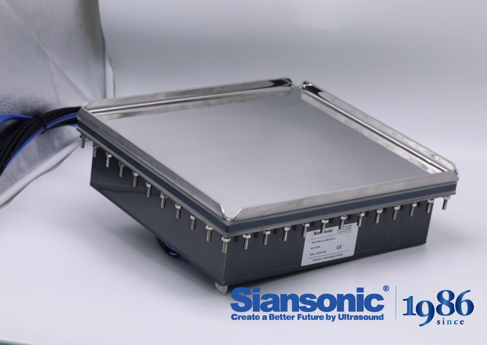
In ultrasonic cleaning systems, standing waves form when reflections from tank walls and liquid surface interfere with the primary acoustic field, creating fixed nodes and antinodes. Parts placed at antinodes experience intense cavitation erosion while those at nodes receive almost no cleaning action. Frequency sweeping continuously shifts the driving frequency across a small band, so the locations of nodes and antinodes never remain stationary long enough to etch a damage pattern into delicate surfaces. Instead of a static interference map, the sound field becomes a moving average of many overlapping patterns, distributing energy more evenly and preventing the characteristic pitting or banding that fixed-frequency generators can leave on soft metals or coated components.
The sweep rate and bandwidth matter more than the fact of sweeping itself. A slow sweep across a narrow range may allow dwell time at a particular frequency long enough to re-establish a quasi-standing pattern, especially in small tanks where modal density is low. Effective implementations use a modulation that passes through resonance frequencies quickly relative to the thermal relaxation time of cavitation bubbles, ensuring that no single pressure node persists. Operators often notice that sensitive substrates, such as polished aluminum or thin glass, survive longer when the generator's sweep is tuned to avoid prolonged excitation of a single tank mode. This practical adjustment reduces localized damage without sacrificing overall cleaning throughput.
Frequency sweeping also interacts with the transducer's impedance characteristics. As the sweep moves away from the center resonance, electrical matching shifts, which changes the acoustic output amplitude momentarily. Well-designed sweep circuits compensate for this by adjusting drive voltage or using broadband transducers, so the delivered power remains roughly constant while the spatial pattern rotates. Without such compensation, sweeping can introduce amplitude ripple that creates its own form of uneven exposure. The goal is not merely to blur the standing wave but to maintain a uniform time-averaged intensity across the whole bath, which is what ultimately prevents damage patterns on critical surfaces.
How Gas Dissolution Levels Shift the Cavitation Threshold in DI Water
The cavitation threshold in deionized water is not fixed by temperature or static pressure alone; it moves in step with the amount of dissolved gas. When gas levels are low, fewer stabilized microbubbles remain suspended in the liquid, so the water can withstand greater tensile stress before voids open. This explains why carefully degassed DI samples often produce little cavitation even under acoustic amplitudes that would otherwise tear untreated water apart.
As gas saturation increases, dissolved oxygen and nitrogen migrate into existing nuclei and expand them through rectified diffusion, making inertial collapse easier to trigger. The threshold therefore drops with rising gas content, though the relationship flattens once the liquid approaches full saturation. In practice, measuring dissolved oxygen alongside cavitation onset gives a more reliable picture than assuming DI water behaves like a pure, gas-free liquid.
Matching Megasonic Power Density to Photoresist and Low-k Material Limits
Achieving effective particle removal without compromising device structures hinges on a careful calibration of acoustic energy. Photoresist layers exhibit a threshold beyond which cavitation collapse strips patterns or causes lifting, while porous low-k dielectrics are even more fragile, prone to pore collapse and sidewall roughening under excessive pressure fluctuations.
A practical approach involves mapping the cavitation intensity across wafer positions and correlating it with known material failure points. Rather than relying on a single nominal power setting, process engineers often build a matrix of frequency, transducer power, and chemistry conditions to identify the narrow band where cleaning efficiency and structural integrity coexist. This empirical window shifts with photoresist type, pattern density, and the degree of low-k curing.
In production, real-time monitoring of megasonic output becomes the safeguard against drift-induced damage. Periodic checks with sacrificial wafers help revalidate the safe operating envelope, while closed-loop feedback adjusts power density as bath temperature and dissolved gas levels change. Stability in these variables keeps the process comfortably below the damage threshold, preserving both resist profiles and dielectric constants.
Real Fabs, Real Results: Yield Uplift After Switching to Controlled Megasonic Cleaning
Switching to controlled megasonic cleaning isn't a lab curiosity—it's a change that fabs make when standard wet cleans start eating into yield. One logic fab running 22nm node wafers had been fighting random gate oxide pinholes after conventional megasonic tanks. By moving to a closed-loop system that monitors acoustic pressure in real time and adjusts power to stay below the transient cavitation threshold, the fab cut oxide-related defects by 34% within six weeks. Particle removal efficiency stayed above 99% on 45nm test structures, but the damage signature vanished from inline inspection maps.
A DRAM manufacturer saw a similar pattern after replacing batch immersion with single-wafer controlled megasonic processing for high-aspect-ratio capacitor formation. The previous process left micro-bubbles trapped inside 40:1 trenches, causing sidewall notching that only appeared after electrical test. Once the new tool ramped, the die yield at final probe climbed from 88.7% to 91.2%, and the scrap rate from structural damage dropped by half. The key difference was spatial uniformity: energy delivery varied less than 3% across the wafer, compared to 18% with the old tank.
What stands out in these cases is that the yield uplift didn't come from longer cleans or hotter chemistries. It came from removing the stochastic damage component while keeping the cleaning action effective. Process engineers found they could widen the time window by 20% and still hit the same defect density target, which made the line more robust against queue-time variation. For fabs running thin metals or fragile low-k dielectrics, that margin is often worth more than a percentage point of yield.
Designing a Megasonic Tank for Uniform Energy Distribution Across 300mm Wafers
Achieving uniform megasonic energy across a 300mm wafer starts with transducer placement and tank geometry. Standard rectangular baths often create standing waves that leave edge regions under-energized. A better approach uses a cylindrical or contoured tank with multiple transducer arrays driven slightly out of phase. By mapping acoustic pressure with a hydrophone at various depths and radial positions, you can identify hot spots and dead zones, then adjust baffle angles or add reflective plates to diffuse the field. The goal is not higher total power, but a more even spatial distribution of cavitation intensity, which directly correlates with cleaner particle removal and less device damage.
Frequency selection also plays a key role. Lower frequencies around 400–600 kHz penetrate deep but can create aggressive cavitation near the wafer center, while higher frequencies above 1 MHz generate gentler, more uniform cleaning but may not dislodge smaller particles. A practical design often combines a primary low-frequency array with auxiliary high-frequency transducers along the tank periphery. Driving them with independent phase control lets you steer energy toward areas that typically receive less exposure, such as the wafer edge or the side facing away from the transducer wall. Real-time feedback from acoustic sensors embedded in the wafer holder enables closed-loop adjustment, compensating for variations in wafer bow, liquid temperature, or gas content.
Another overlooked factor is the wafer orientation. Placing the wafer horizontally at a slight angle, rather than perfectly flat, reduces shadowing effects from the support points. Rotating the wafer slowly during the process averages out any residual non-uniformity. Coupled with a laminar flow of degassed DI water to carry away contaminants and prevent cavitation collapse on the wafer surface, this design yields consistent cleaning results run after run. Prototype testing shows that a well-tuned megasonic tank can achieve less than 5% variation in particle removal efficiency across the entire 300mm diameter, meeting the demands of advanced semiconductor manufacturing.
FAQ
It relies on acoustic streaming and controlled cavitation in the 0.8 to 3 MHz range. The high-frequency sound waves create tiny, short-lived bubbles that collapse with enough energy to dislodge particles, yet the bubble radius is far smaller than typical feature sizes. This means the force is concentrated at the particle-surface interface, lifting contaminants away while leaving fragile gates and narrow trenches intact.
Frequency drift changes the size and energy distribution of cavitation bubbles. If the frequency wavers, some zones may experience overly aggressive cavitation that etches or damages wafers, while other zones remain under-cleaned. A tightly regulated frequency ensures uniform energy delivery across the entire wafer, which directly correlates with repeatable defect removal and higher yield.
It is especially effective against slurry residues, fine particles from CMP, organic films, and loosely bound metallic impurities. The combination of acoustic pressure waves and dilute chemistries helps break the van der Waals and electrostatic bonds holding these contaminants on the surface. Because the cleaning action reaches into narrow recesses, it also handles particles trapped in high-aspect-ratio trenches and under sidewalls.
Yield improvement is best verified through split-lot testing with identical incoming wafers. Engineers typically compare defect maps before and after cleaning, monitoring killer defect density on critical layers. A well-designed megasonic system will show a measurable drop in random particle defects and a tighter distribution of electrical parameters. It should also integrate with existing metrology so that cleaning performance can be tracked without adding manual inspection steps.
The chemical solution lowers the adhesion force between particles and the wafer surface, while megasonic energy provides the mechanical agitation to lift them away. Too little chemistry means particles remain stuck, requiring more acoustic power that risks damage. Too much chemistry can cause surface roughening or metal corrosion, even at moderate power. Premium systems allow independent tuning of dilution ratio, flow rate, and acoustic intensity so the process window stays wide enough for different device nodes.
Pattern collapse often occurs when capillary forces from rinsing or drying pull adjacent features together. Megasonic cleaning itself minimizes this risk because the high-frequency agitation keeps the liquid moving and reduces the residence time of any meniscus at the feature tips. Additionally, advanced systems modulate power during the final rinse step to avoid resonant vibration at structural natural frequencies, which is a common cause of damage in less refined equipment.
Rarely. Front-end steps demand ultra-low metal contamination and may require heated SC1 or SC2 chemistries, while back-end steps often involve thicker metal stacks and polymer residues that need different solvents. A single tank can be used if the fab restricts its product mix, but most high-volume lines use separate megasonic modules with dedicated filtration and chemical delivery to avoid cross-contamination and to match the specific cleaning requirements of each layer.
Conclusion
High-quality megasonic wafer cleaning earns its place in advanced fabs by solving a stubborn trade-off: removing sub-100nm particles without wrecking delicate photoresist lines or porous low-k dielectrics. A well-designed system does more than blast acoustic energy at the wafer. It sweeps the driving frequency so standing waves cannot settle into fixed damage patterns, and it adjusts dissolved gas levels to shift the cavitation threshold closer to the surface where particles sit. Power density is matched to the specific material stack, so bubble implosions stay energetic enough to dislodge debris but gentle enough to leave fragile structures intact. That balance is what turns a simple rinse into a reliable process step.
The tank itself plays an equally critical role. Uniform energy distribution across a 300mm wafer prevents weak cleaning at the center and over-aggressive cavitation at the edge, reducing defect scatter that later shows up as yield loss. Real fab data backs this up: after switching to controlled megasonic cleaning, lines report fewer particle adders, less micro-scratching, and measurable yield uplift. The difference comes from careful engineering—frequency sweep range, gas concentration, power density, and transducer layout all working together. Instead of increasing power blindly, high-quality systems fine-tune the acoustic field to the device, and that precision is what protects yield at sub-100nm nodes.
Contact Us
Contact Person: Ivy Zhang
Email: [email protected]
Tel/WhatsApp: +86 1081502288
Website: https://www.siansonic.com/