

OEM Lost Foam Casting for Complex Metal Parts with Tight Tolerances
2026-10-13
When every millimeter counts and part geometry keeps you up at night, standard casting methods quietly hit their limits. OEM lost foam casting flips that script — it turns near-impossible metal shapes into repeatable, tight-tolerance components without the tooling headaches. At Zhaoyuqi, we’ve built our process around exactly that: complex parts that come out right the first time. This guide walks through what makes lost foam casting the go-to choice for precision OEM work, and where it fits your next project.
Complex Internal Passages Without Removable Cores
Designing cast parts with complex internal passages when removable cores are not an option pushes engineers toward creative solutions like soluble cores, collapsible tooling, or additive manufacturing of the mold itself. The challenge is not just forming the voids, but ensuring they remain clean, dimensionally stable, and accessible for inspection after casting.
One practical route involves printing a ceramic or salt core that can be washed out after solidification, leaving behind intricate channels that would be impossible to machine. Another method uses conformal cooling passages built directly into the mold via laser sintering, bypassing the need for a separate core altogether. The key is matching the core removal method to the alloy, wall thickness, and passage geometry.
In high-pressure die casting, for instance, a collapsible steel core can retract along a curved path to release an undercut, but the mechanism adds cost and maintenance. For lower volumes, investment casting with a 3D-printed wax pattern often proves simpler—each passage is printed hollow, and the wax is melted out later. The real trick is designing the passage network so that no trapped air or core debris remains after burnout.
Holding Tight Tolerances When Every Millimeter Counts
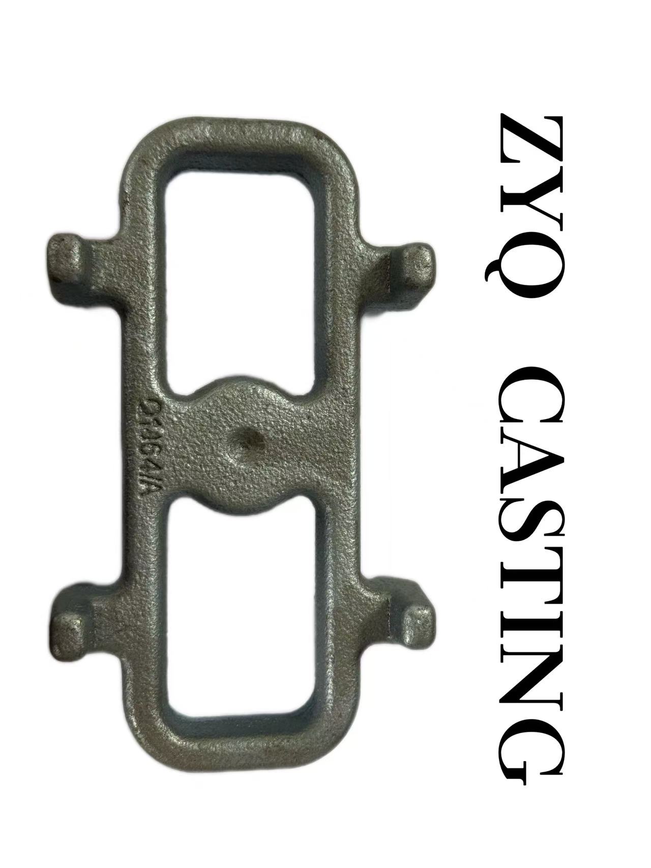
Machining a part to a tolerance of ±0.005 mm is not just about having a good machine. The shop floor temperature shifts by a couple of degrees, the cutting tool wears a few microns after ten parts, and the raw stock carries internal stresses that release unevenly as metal is removed. Ignore any of these and the dimension drifts, often in ways that only show up during final inspection. When a single millimeter is split into two hundred increments, even the oil film on a bearing or the clamping force of a vise becomes a variable you have to control.
One way to stay inside the window is to stop pretending the process is static. Measuring a feature immediately after machining and feeding that data back to the tool offset works, but it only catches drift after it has already happened. Better shops move the measurement earlier, probing the part while it is still in the fixture, then adjusting the next pass before the cut is finished. Laser interferometers and ball-bar tests on the machine axes also reveal errors that a dial indicator will never see. That kind of closed-loop thinking matters because tolerances stack: three features off by 0.003 mm each can leave an assembly 0.009 mm out of square.
Still, no amount of software replaces a machinist who knows the specific machine's personality. Some spindles grow by 0.01 mm during warm-up; some fixtures shift when the hydraulic pressure fluctuates. Holding a tight tolerance for one unit is easy. Holding it across a thousand units means knowing when to change inserts before the wear curve steepens, when to stop for recalibration, and when to reject a setup that is technically within spec but trending the wrong way. That judgment, built from scrapped parts and late nights, is what separates a shop that promises precision from one that delivers it.
Design Rules That Make or Break Lost Foam Castings
In lost foam casting, the pattern is not removed before pouring; it is consumed in place, so wall thickness and section transitions dictate how cleanly that replacement happens. A design that swings from a thick boss to a thin web creates uneven solidification and leaves carbon residue from partially vaporized foam. Uniform walls, generous fillets, and a minimum thickness of about 4 mm for aluminum (slightly more for iron) prevent premature freezing and let the metal front advance without trapping foam gases.
Gating and venting are equally unforgiving. Because the foam must decompose and escape through the refractory coating before metal fills the void, every feature needs a clear path for gas to leave the mold. Blind pockets or long, narrow cores often cause gas porosity or misruns. Designers should add multiple ingates on heavy sections, keep coating permeability consistent with foam density, and avoid sharp internal corners that stall metal flow or crack the delicate foam assembly during compaction.
Alloys That Play Nicely with Lost Foam Dimensional Control
Aluminum-silicon casting alloys, especially A356 and 319, stand out when lost foam dimensional stability is the goal. Their relatively short freezing ranges reduce mushy zone complications, which helps the metal front replace the foam pattern without localized collapse or distortion. Lower pouring temperatures than many other aluminum grades also keep thermal gradients gentle across the thin ceramic shell, so final part dimensions stay closer to the tooling intent.
For ferrous work, ductile iron with carefully managed carbon equivalent behaves well. The graphite expansion during eutectic solidification offsets much of the liquid-to-solid shrinkage, minimizing the need for oversized risers that can disturb the foam pattern. Gray iron benefits similarly, though its flake graphite morphology leaves slightly less predictable contraction in complex sections. Compacted graphite iron sits between the two, offering a practical compromise where dimensional scatter must stay tight.
Some copper-base alloys, particularly aluminum bronzes and certain red brasses, also cooperate with lost foam dimensional control when their freezing range is kept narrow. They do demand closer attention to coating permeability because their higher density can force metal into foam residue too quickly, but once that is dialed in, the as-cast dimensions remain impressively stable compared to sand casting.
The Real Cost of Rework When Tolerances Slip
When a machined part drifts a few microns beyond spec, the immediate fix looks small—another pass on the lathe, a quick adjustment to the tool offset. But those micro-repairs rarely stay contained. A shaft that's slightly undersized forces the bearing fit to be re-evaluated, which pulls a quality engineer off the next job, delays assembly by half a shift, and leaves a bin of questionable parts waiting for disposition. The billable rework might be an hour of machine time; the true cost is the three hours of downstream chaos no one logged.
Tolerance slips also erode trust in the process. Once a batch shows scattered readings near the limit, inspectors start checking every feature instead of sampling, which doubles QA time. Production managers raise the rejection threshold, meaning parts that would have passed last month now get scrapped. And if a suspect lot reaches the customer, the rework moves from your shop floor to a field service truck, where a technician charges travel time, overtime, and a replacement component—plus the quiet damage of a client who now wonders what else wasn't held to print.
The numbers people forget are the ones attached to reordering material, recalibrating machines, and revalidating first articles. A $40 rework on one part can become a $4,000 containment exercise across a shipment. When tolerance slip becomes common, schedules stop being predictions and start being guesses. That is the real cost—not the chip you cut twice, but the planning capacity, supplier confidence, and floor rhythm you lose every time a dimension wanders outside the band.
Measuring What Matters in Complex Cast Geometry
Measuring What Matters in Complex Cast Geometry often means abandoning the false comfort of nominal CAD comparisons and instead asking which surfaces actually locate the part in its assembly. A cast turbocharger housing, for instance, has datum pads that are rarely machined flat; they carry draft, slight shift, and surface texture from the mold. Trying to fixture on those pads as if they were precision-ground datums injects error before a single dimension is taken. The first step is mapping functional datum simulation—using spherical or point contact on the same regions the mating components touch—so the measurement coordinate system reflects how the casting will sit under real loads, not how it sits on a surface plate.
Internal passages and wall stock in complex castings cannot be inferred from external points alone. A water jacket or an oil gallery hidden inside a cylinder head may pass every external check while still having a 40 percent wall thickness variation that compromises fatigue life. Computed tomography and high-energy X-ray now make it possible to extract full volumetric data, but the value lies in aligning that point cloud to the functional datum scheme established earlier. We look at wall thickness distribution relative to core shift, not just minimum values at a handful of cross sections. A thin area adjacent to a thick flange behaves differently from an isolated thin web, and reporting the 95th percentile wall loss tells more than a simple go/no-go gauge ever could.
Curved surfaces on castings—volute tongues, exhaust runners, transition radii—rarely have sharp edges to probe, so the measurement strategy itself becomes a variable. If you instruct a CMM to take 20 points on a blended radius, you will get a number, but that number may reflect probe compensation and point spacing more than the actual geometry. Better practice is to define profile tolerances with explicit datum references and scan the full surface optically, then color-map deviation to the CAD model. This reveals whether the error is systematic, like mold wall movement or shrinkage, or random, like sand inclusion or handling damage. Only then can you decide if the feature is truly out of tolerance or if the tolerance itself was written without understanding how the casting solidifies.
FAQ
Internal passageways, undercuts, and curved profiles that would normally need cores or slides can often be cast as a single piece because the foam pattern vaporizes and leaves the cavity behind.
Gray iron, ductile iron, aluminum-silicon alloys, and some copper-base alloys are everyday choices. Steel is possible but less common due to carbon pickup and surface reactions.
Expect something in the ISO 8062 DCTG 8–10 range depending on size, or roughly ±0.3 mm for small features and more for larger dimensions. Tighter spots usually need a secondary machining allowance.
Investment casting generally holds tighter tolerances and gives a smoother surface, but lost foam can be cheaper for larger, bulkier parts and still meets many automotive and industrial tolerance needs without core tooling.
Most lost foam castings land around 125–250 microinches Ra. The foam bead pattern can leave a fine stipple, so critical sealing or bearing faces are normally machined.
It removes the need for cores and parting lines in many designs, so thin walls and intricate passages can be produced closer to net shape. That cuts assembly steps and machining time.
Keep wall transitions gradual, avoid heavy isolated sections, and use ribbing instead of thick bosses. Draft is rarely needed on the final cast geometry, although the foam molding tool may still need a slight release angle for pattern ejection.
Conclusion
Lost foam casting quietly solves a problem most engineers assume is unsolvable: routing convoluted internal passages without designing removable cores. When a manifold or valve body needs water jackets that snake around cylinders, traditional sand casting demands loose pieces that shift during pour. The foam pattern simply vaporizes, leaving those twisted channels exactly where you placed them. But the real test comes when every millimeter counts. Holding ±0.5% on a 600mm housing isn't about luck; it's about knowing how foam density, coating permeability, and metal shrinkage interact before the first pour. Alloys like A356 aluminum and ductile iron respond predictably if you respect their feeding ranges, while some high-zinc alloys fight you the entire time.
Good lost foam design isn't forgiving—thin ribs under 4mm often collapse, and abrupt section changes invite gas defects. The shops that excel treat the foam as a structural member, not just a sacrificial pattern. When tolerances slip, the cost isn't just scrapped castings; it's the hidden rework of machining setups, fixture tweaks, and customer audits. Smart OEMs measure what actually matters: wall thickness at intersections, not just overall envelope dimensions. They map the foam's burn-off rate and coat thickness across every surface. That's how complex parts leave the foundry ready for CNC, not a conversation about who pays for the scrap.
Contact Us
Contact Person: Nico Yin
Email: [email protected]
Tel/WhatsApp: 8618561567088
Website: https://www.ductileironparts.com/