

Plywood Die Board Laser Cutting Machine Company Explains How Laser Precision Improves Die Cutting Efficiency
2026-11-22
A plywood die board may look simple, but small deviations in slot width or kerf angle ripple through every die cutting job that follows. That’s where laser precision changes the calculation. ADEWO focuses on that exact intersection of beam control and board quality, helping shops remove rework instead of absorbing it. This article breaks down what laser accuracy actually does for cutting speed, consistency, and downstream efficiency.
Where Laser Precision Removes Guesswork from Plywood Die Boards
A plywood die board only earns its keep when every blade sits exactly where the artwork demands. Hand-routed slots drift with bit wear, humidity, and the steady pressure of a deadline. Laser cutting replaces that drift with a repeatable centerline: the beam follows the vector file, holding kerf width and corner geometry steady across the full sheet. The result is a board that accepts rule, creasing channel, and ejection rubber without forcing, shimming, or recutting.
That same precision matters most in dense layouts and tight radii. Small bridge points between adjacent cuts survive intact, narrow channels keep their depth, and curved scores no longer flatten into approximations. Because the cutting path comes straight from the design file, a reorder months later lands on the same geometry instead of relying on a hand-traced pattern. The guesswork disappears, and the cutting floor gets a die board that fits the press the first time.
How a Controlled Beam Reduces Rework in Die Cutting
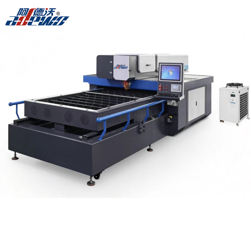
Rework in die cutting often starts with small inconsistencies: a slightly dulled blade, a misregistered sheet, or uneven pressure across the platen. A controlled beam sidesteps many of these problems because it removes material without physical contact. The beam width stays constant from the first cut to the last, so the dimensions do not drift as a die wears. Operators no longer have to compensate for edge rounding or nicks that show up mid-run, which means fewer stops to check and replace tooling.
Another source of rework comes from force-related distortion. Traditional steel rule dies press into the substrate and can shift thin or delicate materials, especially on intricate patterns. The beam follows a predetermined path with no lateral pressure, leaving surrounding areas untouched. This is particularly useful on adhesive-backed stocks or laminated sheets where a small amount of drag can cause layers to separate or stretch. The result is a cleaner first pass and far less time spent sorting, trimming, or re-cutting borderline pieces.
There is also the matter of repeatability across batches. Because the beam path is driven by the same coordinate data each time, the first article and the last article in a production run are cut from the same geometry. When changes are needed, the adjustment happens in the control software rather than by re-machining a physical die. That shortens the feedback loop and keeps rejected parts from piling up while the line waits for a corrected tool.
Why Consistent Kerf Width Speeds Up Assembly
In a shop setting, matching parts is where time disappears. When the kerf width stays the same across every cut, pieces stop needing individual tuning. A tenon cut on one saw matches a slot cut on another, and that alone removes most of the back-and-forth sanding and test fitting.
Consistency also changes how you sequence the work. Instead of measuring, marking, and sneaking up on each joint, you can batch-cut components and trust the fit. The saw kerf becomes a known quantity—like a standard offset—so mating surfaces align the first time. Less trial and error means less clamping, adjusting, and shimming during glue-up.
That predictability matters even more when multiple people are involved. If one person cuts parts in the morning and another assembles them in the afternoon, a steady kerf width keeps the handoff simple. Nobody has to chase small gaps or recut pieces to compensate for a blade that wanders. Assembly turns into a repeatable process rather than a puzzle.
The Real Cost of Manual Adjustments on the Cutting Line
On most cutting lines, a manual tweak here and a quick nudge there hardly raise an eyebrow. The operator steps in, realigns a guide, compensates for drift, and production moves on. But that interruption is rarely as cheap as it looks. Each stop interrupts rhythm, and once the line restarts, the first few cuts often carry the cost of that reset in the form of off-spec edges, scrap, or pieces that need a second pass.
Those minutes add up in ways that don't always appear on a shift report. A line that loses fifteen or twenty minutes a day to manual corrections can quietly surrender dozens of production hours over a month. The more troubling expense is inconsistency: one operator's adjustment may differ from another's, so the same job can leave the floor with slightly different tolerances depending on who was at the controls. That variability tends to surface later as fit-up problems, customer complaints, or rework that consumes even more capacity.
Then there is the wear on people. When manual correction becomes routine, it signals that the process itself is drifting and relying on individual attention to hold quality. Skilled operators end up spending their shifts reacting to small failures instead of improving throughput or handling higher-value work. At that point, the real cost is no longer just downtime or scrap, it's the ceiling the cutting line places on the entire operation.
What Tighter Focus Means for Material Waste and Edge Quality
Cutting with a broader field of view often hides how much scrap is actually being produced. Once the focus narrows, small deviations in edge straightness and kerf width become impossible to ignore. This visibility forces a change in how sheet layouts are planned: instead of accepting a standard margin on every side, operators begin measuring actual cut paths and trimming only what the process truly requires. The result is less skeleton waste, but also a closer match between the programmed contour and the physical edge.
Edge quality shifts in a similar way. Wider settings can mask intermittent dross, slight bevel, or heat discoloration because the eye averages the whole cut face. A tighter focus pulls those inconsistencies forward, making it clear that material grade, assist gas pressure, and nozzle condition matter more than the nominal spot size alone. Adjustments become precise: a half-bar change in gas flow or a small reduction in feed rate can remove the roughness that previously passed unnoticed.
Over time, the habit of inspecting edges at higher magnification changes what counts as acceptable. Parts that once went straight to secondary grinding now need only a light deburring touch. Material waste drops not because a machine was upgraded, but because the operator stopped accepting the margin of invisibility.
Turning Complex Die Profiles into Predictable Production Steps
Complex die profiles rarely fail all at once. They fail at the transitions: a sharp corner that cuts too hot, a relief angle that drifts after heat treat, a blend radius that looks clean on the screen but produces a witness line on the part. Turning those profiles into predictable steps starts with separating the geometry into what can be held, what will move, and what only matters after the tool has settled in the press. Once that split is clear, the machining sequence becomes less about individual features and more about keeping the part stable while the critical surfaces are cut.
A practical approach is to machine the locating surfaces first, then the forming geometry, and leave the least forgiving details for a finishing pass after the die has been through its first thermal cycle. This ordering prevents a hand-polished radius from being destroyed by the next setup or by normal stress relief. It also gives the shop a baseline: if a profile shifts by a few tenths during roughing, that movement is measured before the finish pass, not discovered after assembly.
The final part of making production steps predictable is keeping the process parameters boring. Feeds, speeds, stepover, and coolant pressure should be repeatable enough that the only variable left is the steel itself. When operators stop chasing the profile and start reading the tool wear, the result is a die that fits the press the first time and makes the same part on the last shift as it did on the first.
FAQ
It removes blade deflection and grain tear-out. The beam never pushes against the material, so narrow slots stay consistent and intricate layouts with tight radii can be cut in a single pass without splintering. That eliminates a lot of hand clean-up.
Because kerf width is uniform and edges come out clean, bridges and knockouts fit the CAD intent on the first try. Die makers are not shaving tabs or recutting slots, so a board that used to take hours of fitting can be assembled much sooner.
Mainly in repeatability. Once a CAD file is proven, every following board is cut to the same dimensions. Multi-up layouts stay aligned, so stripping and blanking run with fewer stops, and changeover between jobs drops because you are not swapping worn tooling or resetting jigs.
Yes. The narrow kerf lets you nest die board parts more tightly. There are also fewer rejected boards from overcuts or chipped edges, and less labor tied up in reclaiming or remaking parts.
The laser follows the exact vector path from the CAD drawing, so rule slots land within a few thousandths of an inch. That keeps steel rule straight and matched to the intended cut line, which reduces tonnage variation, uneven wear, and trial cuts on the press.
Modern machines adjust power, speed, and focus for different densities and thicknesses. That keeps edge quality stable whether you are cutting standard maple plywood or a specialty hardwood panel, and it avoids the moisture-related binding sometimes seen with mechanical blades.
Look at beam quality, motion system stiffness, fume extraction, and software that imports native CAD files without conversion issues. Also check whether the supplier has proven cutting parameters for your specific plywood grades instead of offering only generic settings.
Conclusion
Laser precision changes plywood die board work because it removes the variability that hand-guided methods tend to leave behind. Instead of measuring a slot, cutting once, checking the fit, and then trimming again, operators get a controlled beam that holds the kerf width steady from the first board to the last. That consistency matters more than it seems: when every slot accepts the same rule and every bend lands where it should, assembly stops being a series of small corrections. A tighter focal point also leaves cleaner edges, so there is less splintering and less need to sand or scrap borderline pieces. Complex outlines that would normally force a shop to slow down become repeatable production steps, with the beam following the programmed path rather than drifting with operator fatigue or fixture movement.
The hidden expense of manual adjustment is not always visible on a single job, but it accumulates through wasted sheets, extra handling, and machine downtime while someone realigns a guide or re-cuts a mismatched slot. Rework is not just a time problem; it also disturbs the flow of orders that are already queued behind the current board. A laser system lowers that friction by giving the cutting line a predictable reference. When the kerf does not wander and the cut depth remains stable, there are fewer surprises at the fitting table. Edge quality improves because heat-affected damage is kept small, and material waste drops as layouts can be nested more tightly. For a plywood die board company, that combination means the same crew can move from one complex profile to the next without turning every new shape into a guess-and-check exercise.
Contact Us
Contact Person: KAELYN LEE
Email: [email protected]
Tel/WhatsApp: +86 15012673758
Website: https://www.china-adewo.com