

Residual Current Transformer Supplier for Precise Leakage Current Detection and Electrical Protection
2026-08-19
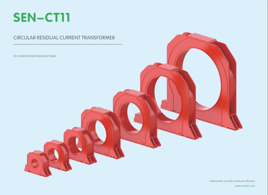
Electrical safety isn’t a place for guesswork. When residual currents start leaking—whether from aging insulation, environmental stress, or equipment faults—you need a residual current transformer (RCT) supplier that treats precision as a non-negotiable. Xiasen has built its reputation on exactly that: detecting the smallest leakage currents before they become real threats. But here's the question most engineers overlook: what separates a truly reliable RCT from one that merely passes the spec sheet? In this post, we’re diving into why precise leakage current detection and robust electrical protection hinge on more than just core material and turns ratio—and how Xiasen's approach changes the game.
Choosing Sensitivity Without Inviting Nuisance Trips
Protective relays and residual current devices often tempt engineers to select the highest possible sensitivity, assuming that earlier detection always means better safety. In practice, this approach can create a different problem: harmless leakage currents, switching transients, or even moisture on insulation produce brief excursions that trip the device for no dangerous reason. Recognizing these nuisance sources is the first step toward a setting that remains quiet during normal operation but still reacts quickly to genuine faults.
A useful strategy is to measure the actual standing leakage on the circuit before choosing a pickup threshold. Long cable runs, power supplies with EMI filters, and variable speed drives all contribute small but steady currents to ground. Setting the trip level above this measured baseline, with a reasonable margin, keeps the device from operating during routine conditions. Adding a short time delay, often just a few hundred milliseconds, can desensitize the device to inrush spikes and capacitor charging events without compromising protection for sustained faults.
It is also worth considering specialized device types rather than relying only on a generic threshold. Some residual current monitors offer frequency-selective or DC-responsive detection, which helps avoid trips caused by harmonics or smooth DC leakage. Where nuisance tripping remains a risk, splitting the installation into smaller protected zones allows a sensitive setting on each branch while keeping the overall system resilient. The goal is not to chase the highest sensitivity number, but to match the protection curve to the real electrical behavior of the load.
Core Materials That Shape Leakage Current Response
The leakage current through an insulating or semiconducting layer is never a simple material constant—it is dictated by the electronic structure and defect landscape of the core material itself. Wide-bandgap oxides like SiO₂ or Al₂O₃, for instance, naturally suppress thermal generation of carriers because their bandgap exceeds several electron volts, yet even these dielectrics can exhibit surprisingly high leakage when metal impurities or oxygen vacancies introduce mid-gap states. These defects act as stepping stones for trap-assisted tunneling, turning what should be a negligible current into a measurable, voltage-dependent flow. The density and energy distribution of such traps, rather than the nominal bandgap alone, often determine the low-field leakage floor.
Moving beyond silicon dioxide, high-k materials such as HfO₂ or ZrO₂ present a different trade-off. Their larger physical thickness for the same capacitance reduces direct tunneling, but the lower conduction band offset with the gate electrode and a higher intrinsic defect density shift the dominant leakage mechanism toward Poole-Frenkel emission or field-enhanced trap ionization. Polymer dielectrics, by contrast, rarely rely on band-to-band transport; their leakage is heavily influenced by ionic impurities, moisture absorption, and space-charge accumulation at electrode interfaces. The same nominal electric field can produce orders-of-magnitude different leakage currents in a polyimide versus a ceramic oxide, simply because the mobile species and charge injection barriers are fundamentally different material properties.
Microstructure adds another layer of control over leakage response. Polycrystalline films, for example, leak preferentially along grain boundaries where broken bonds and segregated impurities lower the local barrier height, while amorphous variants of the same composition can be far more uniform but may suffer from higher intrinsic disorder. Interfacial layers, even a few nanometers thick, can dominate the overall current by imposing their own band offsets or acting as charge trapping regions. Temperature dependence further reveals the material's fingerprint: a leakage current that doubles every 10 °C points to ionic conduction, while a weaker exponential rise suggests tunneling through a fixed barrier. These signatures allow engineers to reverse-engineer which material features—bulk defects, grain boundaries, or interface dipoles—are actually shaping the measured leakage current.
Installation Pitfalls That Undermine Residual Detection
One of the most common installation errors is placing the residual current transformer around a bundle of conductors that includes both the phase and neutral but also the protective earth. On paper this looks harmless, but in practice the earth conductor often carries stray currents from other circuits or from the building's equipotential bonding. Those stray currents flow through the CT core in the opposite direction to the return path on the neutral, partially cancelling the magnetic flux. The result is a residual detector that reads lower than the actual leakage, or sometimes doesn't respond at all until the fault current is dangerously high. Installers who are used to clamping a current probe around a whole cable for convenience tend to repeat the same mistake with residual monitoring, not realising that the CT must see only the live conductors.
Another trap that catches even experienced electricians is an extra neutral-to-earth bond on the load side of the detector. In a standard TN-S system the neutral is earthed only at the supply transformer or the main distribution board. When someone adds a second bond because a sub-panel looks like it needs its own earth reference, a portion of the returning current no longer flows back through the neutral conductor. Instead, it splits off through the protective earth and bypasses the CT. The detector then sees an imbalance that doesn't match the real fault condition. Depending on where the bond is placed, the device may either trip too easily during normal operation or fail to trip during a genuine earth fault. This kind of wiring error is often left in place for years because it doesn't create an immediate short circuit.
Signal wiring from the CT to the relay or controller can also ruin an otherwise good installation. Long, unscreened runs of ordinary wire act like antennas for variable-frequency drive noise, switching transients, and even nearby radio transmitters. The tiny millivolt-level signal from a residual current transformer is easily distorted by this interference, leading to spurious alarms or a false sense of security when the noise masks a real leakage. Some installers try to fix the problem by grounding the screen at both ends, which creates a ground loop and lets circulating currents inject their own error. The proper approach is to use tightly twisted, shielded cable with the screen connected only at the measuring device end, but that detail is easy to overlook when the panel is being wired in a hurry.
Matching Transformers to Breakers for Predictable Coordination
Transformer inrush can easily reach eight to twelve times full-load current for the first few cycles, so a breaker with an instantaneous trip set too aggressively will nuisance trip on energization. Matching starts with comparing the transformer damage curve against the breaker's time-current characteristic, ensuring the protective device clears faults before winding thermal damage occurs but stays above the inrush point. If the breaker curve crosses into the transformer damage region at high fault currents, coordination is lost exactly when it matters most.
A less obvious mismatch comes from breaker short-time delay settings. Many engineers default to a 0.1-second delay, but a transformer with low impedance may produce secondary faults that look very similar to through-faults on the primary. Without proper delay and pickup coordination, a downstream fault can open the upstream transformer breaker first. Checking the thermal withstand at 2 seconds and 5 seconds against the breaker's published curves prevents this hidden loss of selectivity.
The real test occurs when a breaker is replaced or a transformer is uprated. Inrush constants, X/R ratios, and protective relay settings must be re-evaluated together; otherwise the coordination study becomes a paper exercise. A practical approach is to plot both the mechanical and thermal limits of the transformer on the same TCC as the breaker, then verify no overlap below the ANSI withstand points. That single habit eliminates most unpredictable trips.
Dealing with Harmonics and DC Components in Real Circuits
Real circuits rarely behave like their idealized textbook versions. Harmonics creep in when nonlinear loads—think diode rectifiers, switching power supplies, or even slightly saturated transformers—distort the fundamental waveform. These extra frequency components can cause overheating, mis-triggering of control circuits, and electromagnetic interference that frustrates debugging. A practical first step is to inspect the current waveform with a scope: if it looks anything but a clean sine, you are dealing with harmonic content. Passive filters, such as series inductors or shunt capacitor banks tuned near the offending frequency, offer a straightforward way to reduce the worst offenders, though they add bulk and can interact with the source impedance in unexpected ways.
DC components are a quieter but equally troublesome issue. They often appear due to asymmetry in switching circuits, leakage in coupling capacitors, or even a slight DC offset from an op-amp stage. In transformer-coupled systems, even a tiny DC current pushes the core toward saturation, which lowers inductance and distorts the waveform further—a feedback loop that can escalate quickly. The fix often involves a blocking capacitor in series with the transformer primary, or using a servo loop that actively cancels the DC offset. For low-frequency applications, a high-pass filter with a corner well below the operating band can strip out DC without harming the signal, but watch out for phase shift at the band edges.
Measuring and separating these components before they cause damage matters more than any single solution. A true RMS meter will include harmonic energy, while an average-responding meter may hide it—so trust the former when checking for thermal stress. For DC, a simple AC-coupled scope input removes the offset, but you can also measure across a small series resistor with a DC voltmeter to quantify the problem. Once identified, prioritize the source: fix the nonlinear load or asymmetric drive before adding bulky filters. A well-placed active correction circuit, even a simple op-amp integrator, can outperform passive band-aids in many low-power designs. The goal is not to eliminate every harmonic or stray millivolt of DC, but to keep them below the threshold where real components start misbehaving.
Calibration and Testing Habits That Keep Protection Honest
Many protection schemes fail not because of hardware defects but because calibration drift and inadequate testing go unnoticed. You can install the most advanced relay on the market, but if its trip threshold has shifted by a few percent over months, it won't operate when you need it. Routine secondary injection testing—applying known currents and voltages directly to the relay inputs—is one of the most reliable ways to keep it honest. Skipping this step and relying solely on built-in self-checks is like trusting a smoke detector when the battery has been dead for weeks.
Beyond the basic tests, logging every calibration result can reveal slow drift that would otherwise be overlooked. A tiny percentage change might seem harmless, but accumulated over time it can push an overcurrent element's pickup well above the intended setting. Use traceable test equipment and follow consistent procedures so that comparisons between tests are meaningful. If a deviation exceeds the manufacturer's tolerance, don't just tweak it and move on—find out why: it could be aging CTs, loose wiring, or environmental factors.
Finally, testing should mimic the real conditions a protective device will face in the field. Injecting only steady-state sine waves won't expose problems with transient response, harmonics, or CT saturation. Taking the time to simulate fault waveforms with DC offset and saturation effects gives a far more honest evaluation of relay logic. After testing, recheck the settings and trip logic to make sure nobody accidentally changed something during maintenance. This habit takes more effort, but it prevents protection from lying when it matters most.
FAQ
It captures the vector sum of currents flowing through all live conductors. Under normal conditions that sum is essentially zero, so any meaningful output signal indicates leakage current escaping to earth.
Because even small leakage currents can signal insulation breakdown, moisture ingress, or developing faults. Detecting them early lets maintenance teams act before a nuisance trip becomes a safety hazard or an unplanned outage.
Look for a supplier that offers clearly specified accuracy classes, consistent build quality, and practical support for different conductor sizes and mounting conditions. Real application experience matters more than glossy datasheets.
It depends on the design. Some units are optimized for sensitive low-level detection, while others tolerate high primary currents without saturating. Sharing your load profile and leakage thresholds with the supplier helps match the right core and winding configuration.
Cable centering, shielding, and separation from high-current conductors are common oversights. Poor routing can introduce false readings or noise, so the installation guidance from the supplier should cover mechanical fixing, creepage distances, and secondary lead length.
They provide an isolated, proportional signal to relays or controllers, allowing adjustable trip levels, time delays, zone monitoring, and integration with building management systems instead of relying on a fixed built-in threshold.
Relevant references include IEC 61869-2 for current transformers and IEC 62020 for residual current monitoring devices. A supplier should be able to explain which standards apply to their specific accuracy class and insulation ratings.
Conclusion
Selecting a residual current transformer isn't just about picking a sensitivity rating. It means balancing protection thresholds against real-world noise so that a washing machine startup or a variable-speed drive doesn't trigger an unnecessary trip. The magnetic core plays an outsized role here: high-permeability nanocrystalline or permalloy cores catch small leakage currents early, while softer iron-based cores may tolerate transient imbalances without false alarms. A supplier that understands these trade-offs can steer you toward a transformer whose response curve matches the circuit's actual fault profile, rather than simply quoting a datasheet number.
Field installation often decides whether residual detection works as intended. Conductors must pass through the aperture cleanly, shields need proper grounding, and stray magnetic fields from adjacent busbars should be kept at a distance. Pairing the transformer with the correct breaker is equally critical for predictable coordination; otherwise, a genuine earth fault might not clear fast enough or a minor imbalance could cascade into downtime. Real circuits bring harmonics and DC offsets that distort the residual waveform, so the transformer should be specified to handle those components without saturation. Finally, regular calibration and injection testing keep the protection honest, confirming that the installed transformer still reads leakage current within its claimed accuracy band over years of service.
Contact Us
Contact Person: Liu Mengyang
Email: [email protected]
Tel/WhatsApp: 8618727589233
Website: https://www.cnlrm.com/en/